
smfio
![]()
Acknowledgement
--------------------------------------------------------------
This document was originally distributed in text format by
The International MIDI Association.

I have updated it and added new Appendices.

© Copyright 1999 David Back.


EMail: david@csw2.co.uk
Web:   http://www.csw2.co.uk

THIS DOCUMENT MAY BE FREELY COPIED IN WHOLE OR IN PART
PROVIDED THE COPY CONTAINS THIS ACKNOWLEDGEMENT.
--------------------------------------------------------------

SEP-OCT 2018 github.com/tfwio/smfio

- Append/clarify GM2 info/tables
- Format to PDF (mmd->pandoc->xelatex->pdf)
MMA Trademark Policies
The term “MIDI”, the treatment of “MIDI” as used in the MIDI Association1 and MMA logos, and various other logos are all trademarks of the MMA and must only be used as directed below.
MIDI Trademark and Logo
“MIDI” refers to a series of copyrighted specifications (“MMA Specifications”) maintained and published by MMA (and AMEI in Japan). Products, services, and technologies (“Products”) based on the MMA Specifications are known, as “MIDI Products”, “MIDI Files”, etc. MMA has common law and other exclusive rights for the use of the term “MIDI” in conjunction with MMA Specifications and associated Products.
-
The term “MIDI” (whether alone or in conjunction with other terms or modifiers) may be used by other parties (a) in reference to Products that are compliant with MMA Specifications, and/or (b) in the name of a company that provides such Products, except as excluded by paragraph 2 (below). Permitted uses do not need to be approved in advance by MMA. Conversely, any use in reference to non-compliant Products and/or by a company that does not produce Products compliant with MMA Specifications is NOT ALLOWED.
-
The use of the term “MIDI” in combination with other terms or words to identify Products that while compliant with MMA Specifications also have additional functions that are not set forth in an MMA Specification is likely to lead people to expect that MMA has standardized said functions which is deceptive trade practice, false advertising, and unfair competition, and such uses are not allowed by MMA. Only MMA may use the term “MIDI” in conjunction with the naming of a technology or specification.
-
The treatment (font and design) of the term “MIDI” which appears in the MMA and TMA Logo (see web page header, above) and in logos licensed by MMA may not be used by any party without a license from MMA. At this time the only licenses that are available are listed below.
Logo Licenses
The following Logos are available to MMA Members for use with compliant products.
General MIDI Logos
- SMF Logos
- DLS Logos
- XMF Logos
Introduction
This document details the structure of MIDI Files. The purpose of MIDI Files is to provide a way of interchanging time-stamped MIDI data between different programs on the same or different computers. One of the primary design goals is compact representation, which makes it very appropriate for disk-based file format, but which might make it inappropriate for storing in memory for quick access by a sequencer program.
MIDI Files contain one or more MIDI streams, with time information for each event. Song, sequence, and track structures, tempo and time signature information, are all supported. Track names and other descriptive information may be stored with the MIDI data. This format supports multiple tracks and multiple sequences so that if the user of a program which supports multiple tracks intends to move a file to another one, this format can allow that to happen.
The specification defines the 8-bit binary data stream used in the file. The data can be stored in a binary file, nibbilized, 7-bit-ized for efficient MIDI transmission, converted to Hex ASCII, or translated symbolically to a printable text file. This spec addresses what’s in the 8-bit stream. It does not address how a MIDI File will be transmitted over MIDI.
Sequences, Tracks, Chunks: File Block Structure
In this document, bit 0 means the least significant bit of a byte, and bit 7 is the most significant.
Variable Length Quantity
Some numbers in MIDI Files are represented in a form called VARIABLE-LENGTH QUANTITY. These numbers are represented 7 bits per byte, most significant bits first. All bytes except the last have bit 7 set, and the last byte has bit 7 clear. If the number is between 0 and 127, it is thus represented exactly as one byte.
Some examples of numbers represented as variable-length quantities:
00000000 → 00
00000040 → 40
0000007F → 7F
00000080 → 81 00
00002000 → C0 00
00003FFF → FF 7F
00004000 → 81 80 00
00100000 → C0 80 00
001FFFFF → FF FF 7F
00200000 → 81 80 80 00
08000000 → C0 80 80 00
0FFFFFFF → FF FF FF 7F
The largest number which is allowed is 0FFFFFFF so that the variable-length
representations must fit in 32 bits in a routine to write variable-length
numbers. Theoretically, larger numbers are possible, but 2 x 10^8^
96^ths^ of a beat at a fast tempo of 500 beats per minute is four days,
long enough for any delta-time!
Files
To any file system, a MIDI File is simply a series of 8-bit bytes. On the Macintosh, this byte stream is stored in the data fork of a file (with file type ‘MIDI’), or on the Clipboard (with data type ‘MIDI’). Most other computers store 8-bit byte streams in files.
Chunks
MIDI Files are made up of -chunks-. Each chunk has a 4-character type and a 32-bit length, which is the number of bytes in the chunk. This structure allows future chunk types to be designed which may be easily be ignored if encountered by a program written before the chunk type is introduced. Your programs should EXPECT alien chunks and treat them as if they weren’t there.
Each chunk begins with a 4-character ASCII type. It is followed by a 32-bit
length, most significant byte first (a length of 6 is stored as 00 00 00 06).
This length refers to the number of bytes of data which follow: the eight
bytes of type and length are not included. Therefore, a chunk with a length
of 6 would actually occupy 14 bytes in the disk file.
This chunk architecture is similar to that used by Electronic Arts’ IFF
format, and the chunks described herein could easily be placed in an IFF
file. The MIDI File itself is not an IFF file: it contains no nested chunks,
and chunks are not constrained to be an even number of bytes long. Converting
it to an IFF file is as easy as padding odd length chunks, and sticking the
whole thing inside a FORM chunk.
Chunk Types
MIDI Files contain two types of chunks: header chunks and track chunks. A -header- chunk provides a minimal amount of information pertaining to the entire MIDI file. A -track- chunk contains a sequential stream of MIDI data which may contain information for up to 16 MIDI channels. The concepts of multiple tracks, multiple MIDI outputs, patterns, sequences, and songs may all be implemented using several track chunks.
A MIDI File always starts with a header chunk, and is followed by one or more track chunks.
MThd <length of header data>
<header data>
MTrk <length of track data>
<track data>
MTrk <length of track data>
<track data>
…
Chunk Descriptions
Header Chunks
The header chunk at the beginning of the file specifies some basic
information about the data in the file.
Here’s the syntax of the complete chunk:
<Header Chunk> = <chunk type><length><format><ntrks><division>
As described above, <chunk type> is the four ASCII characters ‘MThd’;
<length> is a 32-bit representation of the number 6 (high byte first).
The data section contains three 16-bit words, stored most-significant byte first.
The first word, <format>, specifies the overall organisation of the file.
Only three values of <format> are specified:
| Format | Description |
|---|---|
| 0 | the file contains a single multi-channel track |
| 1 | the file contains one or more simultaneous tracks (or MIDI outputs) of a sequence |
| 2 | the file contains one or more sequentially independent single-track patterns |
More information about these formats is provided below.
The next word, <ntrks>, is the number of track chunks in the file. It will
always be 1 for a format 0 file.
The third word, <division>, specifies the meaning of the delta-times. It
has two formats, one for metrical time, and one for time-code-based time:
| bit 15 | bits 14 thru 8 | bits 7 thru 0 |
|---|---|---|
| 0 | ticks per quarter-note | |
| 1 | negative SMPTE format | ticks per frame |
If bit 15 of <division> is zero, the bits 14 thru 0 represent the number of
delta time “ticks” which make up a quarter-note. For instance, if division is
96, then a time interval of an eighth-note between two events in the file
would be 48.
If bit 15 of <division> is a one, delta times in a file correspond to
subdivisions of a second, in a way consistent with SMPTE2 and MIDI
Time Code. Bits 14 thru 8 contain one of the four values -24, -25, -29, or
-30, corresponding to the four standard SMPTE and MIDI Time Code formats (-29
corresponds to 30 drop frame), and represents the number of frames per
second. These negative numbers are stored in two’s compliment form. The
second byte (stored positive) is the resolution within a frame: typical
values may be 4 (MIDI Time Code resolution), 8, 10, 80 (bit resolution), or 100.
This stream allows exact specifications of time-code-based tracks, but
also allows millisecond-based tracks by specifying 25 frames/sec and a
resolution of 40 units per frame. If the events in a file are stored with a
bit resolution of thirty-frame time code, the division word would be E250
hex.
MIDI File Formats 0, 1 and 2
A Format 0 file has a header chunk followed by one track chunk. It is the most interchangeable representation of data. It is very useful for a simple single-track player in a program which needs to make synthesisers make sounds, but which is primarily concerned with something else such as mixers or sound effect boxes. It is very desirable to be able to produce such a format, even if your program is track-based, in order to work with these simple programs.
A Format 1 or 2 file has a header chunk followed by one or more track chunks. programs which support several simultaneous tracks should be able to save and read data in format 1, a vertically one dimensional form, that is, as a collection of tracks. Programs which support several independent patterns should be able to save and read data in format 2, a horizontally one dimensional form. Providing these minimum capabilities will ensure maximum interchangeability.
In a MIDI system with a computer and a SMPTE synchroniser which uses Song
Pointer and Timing Clock, tempo maps (which describe the tempo throughout the
track, and may also include time signature information, so that the bar
number may be derived) are generally created on the computer. To use them
with the synchroniser, it is necessary to transfer them from the computer. To
make it easy for the synchroniser to extract this data from a MIDI File,
tempo information should always be stored in the first MTrk chunk. For a
format 0 file, the tempo will be scattered through the track and the tempo
map reader should ignore the intervening events; for a format 1 file, the
tempo map must be stored as the first track. It is polite to a tempo map
reader to offer your user the ability to make a format 0 file with just the
tempo, unless you can use format 1.
All MIDI Files should specify tempo and time signature. If they don’t, the time signature is assumed to be , and the tempo 120 beats per minute. In format 0, these meta-events should occur at least at the beginning of the single multi-channel track. In format 1, these meta-events should be contained in the first track. In format 2, each of the temporally independent patterns should contain at least initial time signature and tempo information.
Format IDs to support other structures may be defined in the future. A
program encountering an unknown format ID may still read other MTrk chunks
it finds from the file, as format 1 or 2, if its user can make sense of them
and arrange them into some other structure if appropriate. Also, more
parameters may be added to the MThd chunk in the future: it is important to
read and honour the length, even if it is longer than 6.
Track Chunks
The track chunks (type MTrk) are where actual song data is stored. Each track
chunk is simply a stream of MIDI events (and non-MIDI events), preceded by
delta-time values. The format for Track Chunks (described below) is exactly
the same for all three formats (0, 1, and 2: see
“[Header Chunk][Header Chunks]” above) of MIDI Files.
MTrk chunk
Here is the syntax of an MTrk chunk (the + means “one or more”: at least one
MTrk event must be present):
<Track Chunk> = <chunk type><length><MTrk event>+
The syntax of an MTrk event is very simple:
<MTrk event> = <delta-time><event>
delta-time
<delta-time> is stored as a variable-length quantity. It represents the
amount of time before the following event. If the first event in a track
occurs at the very beginning of a track, or if two events occur
simultaneously, a delta-time of zero is used. Delta-times are always
present. (Not storing delta-times of 0 requires at least two bytes for any
other value, and most delta-times aren’t zero.) Delta-time is in some
fraction of a beat (or a second, for recording a track with SMPTE times), as
specified in the header chunk.
<event> = <MIDI event> | <sysex event> | <meta-event>
MIDI event
<MIDI event> is any MIDI channel message See Appendix 1 - [MIDI Messages].
Running status is used: status bytes of MIDI channel messages may be omitted
if the preceding event is a MIDI channel message with the same status. The
first event in each MTrk chunk must specify status. Delta-time is not
considered an event itself: it is an integral part of the syntax for an MTrk
event. Notice that running status occurs across delta-times.
sysex event
<sysex event> is used to specify a MIDI system exclusive message, either as
one unit or in packets, or as an “escape” to specify any arbitrary bytes to
be transmitted. See Appendix 1 - [MIDI Messages]. A normal complete system
exclusive message is stored in a MIDI File in this way:
F0 <length> <bytes to be transmitted after F0>
The length is stored as a variable-length quantity. It specifies the number
of bytes which follow it, not including the F0 or the length itself. For
instance, the transmitted message F0 43 12 00 07 F7 would be stored in a
MIDI File as F0 05 43 12 00 07 F7. It is required to include the F7 at the
end so that the reader of the MIDI File knows that it has read the entire
message.
Another form of sysex event is provided which does not imply that an F0
should be transmitted. This may be used as an “escape” to provide for the
transmission of things which would not otherwise be legal, including system
realtime messages, song pointer or select, MIDI Time Code, etc. This uses the
F7 code:
F7 <length> <all bytes to be transmitted>
Unfortunately, some synthesiser manufacturers specify that their system
exclusive messages are to be transmitted as little packets. Each packet is
only part of an entire syntactical system exclusive message, but the times
they are transmitted are important. Examples of this are the bytes sent in a
CZ patch dump, or the FB-01’s “system exclusive mode” in which microtonal
data can be transmitted. The F0 and F7 sysex events may be used together
to break up syntactically complete system exclusive messages into timed
packets.
An F0 sysex event is used for the first packet in a series – it is a
message in which the F0 should be transmitted. An F7 sysex event is used
for the remainder of the packets, which do not begin with F0. (Of course,
the F7 is not considered part of the system exclusive message).
A syntactic system exclusive message must always end with an F7, even if the
real-life device didn’t send one, so that you know when you’ve reached the
end of an entire sysex message without looking ahead to the next event in the
MIDI File. If it’s stored in one complete F0 sysex event, the last byte must
be an F7. There also must not be any transmittable MIDI events in between
the packets of a multi-packet system exclusive message. This principle is
illustrated in the paragraph below.
Here is a MIDI File of a multi-packet system exclusive message: suppose the
bytes F0 43 12 00 were to be sent, followed by a 200-tick delay, followed by
the bytes 43 12 00 43 12 00, followed by a 100-tick delay, followed by the
bytes 43 12 00 F7, this would be in the MIDI File:
| hex | value |
|---|---|
| F0 03 43 12 00 | |
| 81 48 | 200-tick delta time |
| F7 06 43 12 00 43 12 00 | |
| 64 | 100-tick delta time |
| F7 04 43 12 00 F7 |
When reading a MIDI File, and an F7 sysex event is encountered without a
preceding F0 sysex event to start a multi-packet system exclusive message
sequence, it should be presumed that the F7 event is being used as an
“escape”. In this case, it is not necessary that it end with an F7, unless
it is desired that the F7 be transmitted.
meta-event
<meta-event> specifies non-MIDI information useful to this format or to
sequencers, with this syntax:
FF <type> <length> <bytes>
All meta-events begin with FF, then have an event type byte (which is always
less than 128), and then have the length of the data stored as a
variable-length quantity, and then the data itself. If there is no data, the
length is 0. As with chunks, future meta-events may be designed which may not
be known to existing programs, so programs must properly ignore meta-events
which they do not recognise, and indeed should expect to see them. Programs
must never ignore the length of a meta-event which they do not recognise, and
they shouldn’t be surprised if it’s bigger than expected. If so, they must
ignore everything past what they know about. However, they must not add
anything of their own to the end of the meta-event. Sysex events and meta
events cancel any running status which was in effect. Running status does not
apply to and may not be used for these messages.
Meta-Events
A few meta-events are defined herein. It is not required for every program to support every meta-event.
In the syntax descriptions for each of the meta-events a set of conventions
is used to describe parameters of the events. The FF which begins each event,
the type of each event, and the lengths of events which do not have a
variable amount of data are given directly in hexadecimal. A notation such as
dd or se, which consists of two lower-case letters, mnemonically
represents an 8-bit value. Four identical lower-case letters such as wwww
mnemonically refer to a 16-bit value, stored most-significant-byte first. Six
identical lower-case letters such as tttttt refer to a 24-bit value, stored
most-significant-byte first. The notation len refers to the length portion
of the meta-event syntax, that is, a number, stored as a variable- length
quantity, which specifies how many bytes (possibly text) data were just
specified by the length.
In general, meta-events in a track which occur at the same time may occur in any order. If a copyright event is used, it should be placed as early as possible in the file, so it will be noticed easily. Sequence Number and Sequence/Track Name events, if present, must appear at time 0. An end-of-track event must occur as the last event in the track.
Meta-Event Definitions
FF 00 02 Sequence Number
This optional event, which must occur at the beginning of a track, before any nonzero delta-times, and before any transmittable MIDI events, specifies the number of a sequence. In a format 2 MIDI File, it is used to identify each “pattern” so that a “song” sequence using the Cue message can refer to the patterns. If the ID numbers are omitted, the sequences’ locations in order in the file are used as defaults. In a format 0 or 1 MIDI File, which only contain one sequence, this number should be contained in the first (or only) track. If transfer of several multitrack sequences is required, this must be done as a group of format 1 files, each with a different sequence number.
FF 01 len text Text Event
Any amount of text describing anything. It is a good idea to put a text event right at the beginning of a track, with the name of the track, a description of its intended orchestration, and any other information which the user wants to put there. Text events may also occur at other times in a track, to be used as lyrics, or descriptions of cue points. The text in this event should be printable ASCII characters for maximum interchange. However, other character codes using the high-order bit may be used for interchange of files between different programs on the same computer which supports an extended character set. Programs on a computer which does not support non-ASCII characters should ignore those characters.
Meta-event types 01 through 0F are reserved for various types of text
events, each of which meets the specification of text events (above) but is
used for a different purpose:
FF 02 len text Copyright Notice
Contains a copyright notice as printable ASCII text. The notice should contain the characters (C), the year of the copyright, and the owner of the copyright. If several pieces of music are in the same MIDI File, all of the copyright notices should be placed together in this event so that it will be at the beginning of the file. This event should be the first event in the track chunk, at time 0.
FF 03 len text Sequence/Track Name
If in a format 0 track, or the first track in a format 1 file, the name of the sequence. Otherwise, the name of the track.
FF 04 len text Instrument Name
A description of the type of instrumentation to be used in that track. May be used with the MIDI Prefix meta-event to specify which MIDI channel the description applies to, or the channel may be specified as text in the event itself.
FF 05 len text Lyric
A lyric to be sung. Generally, each syllable will be a separate lyric event which begins at the event’s time.
FF 06 len text Marker
Normally in a format 0 track, or the first track in a format 1 file. The name of that point in the sequence, such as a rehearsal letter or section name (“First Verse”, etc.)
FF 07 len text Cue Point
A description of something happening on a film or video screen or stage at that point in the musical score (“Car crashes into house”, “curtain opens”, “she slaps his face”, etc.)
FF 20 01 cc MIDI Channel Prefix
The MIDI channel (0-15) contained in this event may be used to associate a MIDI channel with all events which follow, including System exclusive and meta-events. This channel is “effective” until the next normal MIDI event (which contains a channel) or the next MIDI Channel Prefix meta-event. If MIDI channels refer to “tracks”, this message may be put into a format 0 file, keeping their non-MIDI data associated with a track. This capability is also present in Yamaha’s ESEQ file format.
FF 2F 00 End of Track
This event is not optional. It is included so that an exact ending point may be specified for the track, so that an exact length is defined, which is necessary for tracks which are looped or concatenated.
FF 51 03 tttttt Set Tempo (in microseconds per MIDI quarter-note)
This event indicates a tempo change. Another way of putting “microseconds per quarter-note” is “24^ths^ of a microsecond per MIDI clock”. Representing tempos as time per beat instead of beat per time allows absolutely exact long-term synchronisation with a time-based sync protocol such as SMPTE time code or MIDI time code. The amount of accuracy provided by this tempo resolution allows a four-minute piece at 120 beats per minute to be accurate within 500 usec3 at the end of the piece. Ideally, these events should only occur where MIDI clocks would be located – this convention is intended to guarantee, or at least increase the likelihood, of compatibility with other synchronisation devices so that a time signature/tempo map stored in this format may easily be transferred to another device.
FF 54 05 hr mn se fr ff SMPTE Offset
This event, if present, designates the SMPTE time at which the track chunk is supposed to start. It should be present at the beginning of the track, that is, before any nonzero delta-times, and before any transmittable MIDI events. the hour must be encoded with the SMPTE format, just as it is in MIDI Time Code. In a format 1 file, the SMPTE Offset must be stored with the tempo map, and has no meaning in any of the other tracks. The ff field contains fractional frames, in 100ths of a frame, even in SMPTE-based tracks which specify a different frame subdivision for delta-times.
FF 58 04 nn dd cc bb Time Signature
The time signature is expressed as four numbers. nn and dd represent the numerator and denominator of the time signature as it would be notated. The denominator is a negative power of two: 2 represents a quarter-note, 3 represents an eighth-note, etc. The cc parameter expresses the number of MIDI clocks in a metronome click. The bb parameter expresses the number of notated 32nd-notes in a MIDI quarter-note (24 MIDI clocks). This was added because there are already multiple programs which allow a user to specify that what MIDI thinks of as a quarter-note (24 clocks) is to be notated as, or related to in terms of, something else.
Therefore, the complete event for time, where the metronome clicks every three eighth-notes, but there are 24 clocks per quarter-note, 72 to the bar, would be (in hex):
FF 58 04 06 03 24 08
That is, time (8 is 2 to the 3rd power, so this is 06 03), 36
MIDI clocks per dotted-quarter (24 hex!), and eight notated 32nd-notes
per quarter-note.
FF 59 02 sf mi Key Signature
sf = -7: 7 flats
sf = -1: 1 flat
sf = 0: key of C
sf = 1: 1 sharp
sf = 7: 7 sharps

mi = 0: major key
mi = 1: minor key
FF 7F len data Sequencer Specific Meta-Event
Special requirements for particular sequencers may use this event type: the first byte or bytes of data is a manufacturer ID (these are one byte, or if the first byte is 00, three bytes). As with MIDI System Exclusive, manufacturers who define something using this meta-event should publish it so that others may be used by a sequencer which elects to use this as its only file format; sequencers with their established feature-specific formats should probably stick to the standard features when using this format.
See Appendix 2 - [Program Fragments and Example MIDI Files]
Appendix
MIDI Messages
A MIDI message is made up of an eight-bit status byte which is generally followed by one or two data bytes. There are a number of different types of MIDI messages. At the highest level, MIDI messages are classified as being either Channel Messages or System Messages. Channel messages are those which apply to a specific Channel, and the Channel number is included in the status byte for these messages. System messages are not Channel specific, and no Channel number is indicated in their status bytes.
Channel Messages may be further classified as being either Channel Voice Messages, or Mode Messages. Channel Voice Messages carry musical performance data, and these messages comprise most of the traffic in a typical MIDI data stream. Channel Mode messages affect the way a receiving instrument will respond to the Channel Voice messages.
MIDI System Messages are classified as being System Common Messages, System Real Time Messages, or System Exclusive Messages. System Common messages are intended for all receivers in the system. System Real Time messages are used for synchronisation between clock-based MIDI components. System Exclusive messages include a Manufacturer’s Identification (ID) code, and are used to transfer any number of data bytes in a format specified by the referenced manufacturer.
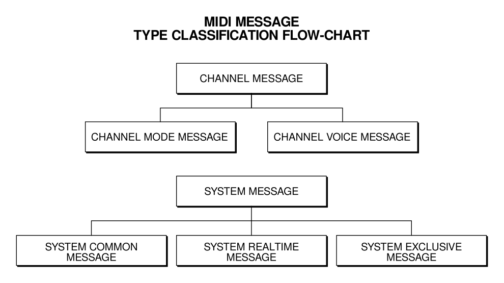
Table of Major MIDI Messages
Channel Voice Messages
| bin stat | data D7-D0 stat |
hex | Description |
|---|---|---|---|
1000nnnn |
0kkkkkkk 0vvvvvvv |
0x8n |
Note Off event. This message is sent when a note is released (ended). kkkkkkk is the key (note) number.vvvvvvv is the velocity. |
1001nnnn |
0kkkkkkk 0vvvvvvv |
0x9n |
Note On event. This message is sent when a note is depressed (start). kkkkkkk is the key (note) number.vvvvvvv is the velocity. |
1010nnnn |
0kkkkkkk 0vvvvvvv |
0xAn |
Polyphonic Key Pressure (Aftertouch). This message is sent when a note is depressed (start). kkkkkkk is the key (note) number.vvvvvvv is the velocity. |
1011nnnn |
0kkkkkkk 0vvvvvvv |
0xBn |
Control Change. This message is sent when a controller value changes. Controllers include devices such as pedals and levers. Certain controller numbers are reserved for specific purposes. See [Channel Mode Messages]. ccccccc is the controller number.vvvvvvv is the new value. |
1100nnnn |
0ppppppp |
0xCn |
Program Change. This message sent when the patch number changes. ppppppp is the new program number. |
1101nnnn |
0vvvvvvv |
0xDn |
Channel Pressure (After-touch). This message is most often sent by pressing down on the key after it “bottoms out”. This message is different from polyphonic after-touch. Use this message to send the single greatest pressure value (of all the current depressed keys). vvvvvvv is the pressure value. |
1110nnnn |
0lllllll |
0xEn |
Pitch Wheel Change.0mmmmmmm This message is sent to indicate a change in the pitch wheel.The pitch wheel is measured by a fourteen bit value. Centre (no pitch change) is 2000H. Sensitivity is a function of the transmitter. lllllll are the least significant 7 bits.mmmmmmm are the most significant 7 bits. |
Table: Channel Voice Messages
Channel Mode Messages
(See also Control Change, above)
| byte status | data bytes 7-0 | Description |
|---|---|---|
1011nnnn |
0ccccccc |
Channel Mode Messages.0vvvvvvv This the same code as the Control Change (above), but implements Mode control by using reserved controller numbers.The numbers are: Local Control. When Local Control is Off, all devices on a given channel will respond only to data received over MIDI. Played data, etc. will be ignored.Local Control On restores the functions of the normal controllers.c = 122, v = 0: Local Control Offc = 122, v = 127: Local Control OnAll Notes Off. When an All Notes Off is received all oscillators will turn off. c = 123, v = 0: All Notes Offc = 124, v = 0: Omni Mode Offc = 125, v = 0: Omni Mode Onc = 126, v = M: Mono Mode On (Poly Off) where M is the number of channels (Omni Off) or 0 (Omni On)c = 127, v = 0: Poly Mode On (Mono Off)(Note: These four messages also cause All Notes Off) |
Table: Channel Mode Messages
System Common Messages
| byte status | data bytes | D7-D0 |
hex status | Description |
|---|---|---|---|---|
11110000 |
0iiiiiii |
.. .. 0ddddddd 11110111 |
0xF0 |
System Exclusive.0dddddddThis message makes up for all that MIDI doesn’t support. iiiiiii is usually a seven-bit Manufacturer’s I.D. code. If the synthesiser recognises the I.D. code as its own, it will listen to the rest of the message ddddddd. Otherwise, the message will be ignored. System Exclusive is used to send bulk dumps such as patch parameters and other non-spec data. (Note: Real-Time messages ONLY may be interleaved with a System Exclusive.) This message also is used for extensions called Universal Exclusive Messages. |
11110001 |
0xF1 |
Undefined. | ||
11110010 |
0lllllll |
0mmmmmmm |
0xF2 |
Song Position Pointer. This is an internal 14 bit register that holds the number of MIDI beats (1 beat=six MIDI clocks) since the start of the song. l is the LSB, m the MSB. |
11110011 |
0sssssss |
0xF3 |
Song Select. The Song Select specifies which sequence or song is to be played. |
|
11110100 |
0xF4 |
Undefined. | ||
11110101 |
0xF5 |
Undefined. | ||
11110110 |
0xF6 |
Tune Request. Upon receiving a Tune Request, all analog synthesisers should tune their oscillators. |
||
11110111 |
0xF7 |
End of Exclusive. Used to terminate a System Exclusive dump (see above). |
Table: System Common Messages
System Realtime Messages
| byte status | data bytes D7-D0 |
hex status | Description |
|---|---|---|---|
11111000 |
0xF8 |
Timing Clock. Sent 24 times per quarter note when synchronisation is required. |
|
11111001 |
0xF9 |
Undefined. | |
11111010 |
0xFA |
Start. Start the current sequence playing. (This message will be followed with Timing Clocks). |
|
11111011 |
0xFB |
Continue. Continue at the point the sequence was Stopped. |
|
11111100 |
0xFC |
Stop. Stop the current sequence. |
|
11111101 |
0xFD |
Undefined. | |
11111110 |
0xFE |
Active Sensing. Use of this message is optional. When initially sent, the receiver will expect to receive another Active Sensing message each 300ms (max), or it will be assume that the connection has been terminated. At termination, the receiver will turn off all voices and return to normal (non-active sensing) operation. |
|
11111111 |
0xFF |
Reset Reset all receivers in the system to power-up status. This should be used sparingly, preferably under manual control. In particular, it should not be sent on power-up. In a MIDI file this is used as an escape to introduce <meta events>. |
Table: System Realtime Messages
Table of MIDI Controller Messages
[2nd byte {bin,hex,dec}, function, 3rd byte {Value,Use}]
| bin | hex | dec | Function | Value | Use |
|---|---|---|---|---|---|
00000000 |
00 |
0 |
Bank Select (MSB:0, LSB:32) GM2 | 0-127 |
MSB |
00000001 |
01 |
1 |
* Modulation wheel (Depth) GM2 | 0-127 |
MSB |
00000010 |
02 |
2 |
Breath control | 0-127 |
MSB |
00000011 |
03 |
3 |
Undefined | 0-127 |
MSB |
00000100 |
04 |
4 |
Foot controller | 0-127 |
MSB |
00000101 |
05 |
5 |
Portamento time GM2 | 0-127 |
MSB |
00000110 |
06 |
6 |
Data Entry GM2 | 0-127 |
MSB |
00000111 |
07 |
7 |
* Channel Volume (GM1 Main Volume) GM2 | 0-127 |
MSB |
00001000 |
08 |
8 |
Balance | 0-127 |
MSB |
00001001 |
09 |
9 |
Undefined | 0-127 |
MSB |
00001010 |
0A |
10 |
* Pan GM2 | 0-127 |
MSB |
00001011 |
0B |
11 |
* Expression Controller GM2 | 0-127 |
MSB |
00001100 |
0C |
12 |
Effect control 1 | 0-127 |
MSB |
00001101 |
0D |
13 |
Effect control 2 | 0-127 |
MSB |
00001110 |
0E |
14 |
Undefined | 0-127 |
MSB |
00001111 |
0F |
15 |
Undefined | 0-127 |
MSB |
00010000 |
10 |
16 |
General Purpose Controller #1 | 0-127 |
MSB |
00010001 |
11 |
17 |
General Purpose Controller #2 | 0-127 |
MSB |
00010010 |
12 |
18 |
General Purpose Controller #3 | 0-127 |
MSB |
00010011 |
13 |
19 |
General Purpose Controller #4 | 0-127 |
MSB |
00010100 |
14 |
20 |
Undefined | 0-127 |
MSB |
00010101 |
15 |
21 |
Undefined | 0-127 |
MSB |
00010110 |
16 |
22 |
Undefined | 0-127 |
MSB |
00010111 |
17 |
23 |
Undefined | 0-127 |
MSB |
00011000 |
18 |
24 |
Undefined | 0-127 |
MSB |
00011001 |
19 |
25 |
Undefined | 0-127 |
MSB |
00011010 |
1A |
26 |
Undefined | 0-127 |
MSB |
00011011 |
1B |
27 |
Undefined | 0-127 |
MSB |
00011100 |
1C |
28 |
Undefined | 0-127 |
MSB |
00011101 |
1D |
29 |
Undefined | 0-127 |
MSB |
00011110 |
1E |
30 |
Undefined | 0-127 |
MSB |
00011111 |
1F |
31 |
Undefined | 0-127 |
MSB |
00100000 |
20 |
32 |
Bank Select | 0-127 |
LSB |
00100001 |
21 |
33 |
Modulation wheel | 0-127 |
LSB |
00100010 |
22 |
34 |
Breath control | 0-127 |
LSB |
00100011 |
23 |
35 |
Undefined | 0-127 |
LSB |
00100100 |
24 |
36 |
Foot controller | 0-127 |
LSB |
00100101 |
25 |
37 |
Portamento time | 0-127 |
LSB |
00100110 |
26 |
38 |
Data entry GM2 | 0-127 |
LSB |
00100111 |
27 |
39 |
Channel Volume (formerly Main Volume) | 0-127 |
LSB |
00101000 |
28 |
40 |
Balance | 0-127 |
LSB |
00101001 |
29 |
41 |
Undefined | 0-127 |
LSB |
00101010 |
2A |
42 |
Pan | 0-127 |
LSB |
00101011 |
2B |
43 |
Expression Controller | 0-127 |
LSB |
00101100 |
2C |
44 |
Effect control 1 | 0-127 |
LSB |
00101101 |
2D |
45 |
Effect control 2 | 0-127 |
LSB |
00101110 |
2E |
46 |
Undefined | 0-127 |
LSB |
00101111 |
2F |
47 |
Undefined | 0-127 |
LSB |
00110000 |
30 |
48 |
General Purpose Controller #1 | 0-127 |
LSB |
00110001 |
31 |
49 |
General Purpose Controller #2 | 0-127 |
LSB |
00110010 |
32 |
50 |
General Purpose Controller #3 | 0-127 |
LSB |
00110011 |
33 |
51 |
General Purpose Controller #4 | 0-127 |
LSB |
00110100 |
34 |
52 |
Undefined | 0-127 |
LSB |
00110101 |
35 |
53 |
Undefined | 0-127 |
LSB |
00110110 |
36 |
54 |
Undefined | 0-127 |
LSB |
00110111 |
37 |
55 |
Undefined | 0-127 |
LSB |
00111000 |
38 |
56 |
Undefined | 0-127 |
LSB |
00111001 |
39 |
57 |
Undefined | 0-127 |
LSB |
00111010 |
3A |
58 |
Undefined | 0-127 |
LSB |
00111011 |
3B |
59 |
Undefined | 0-127 |
LSB |
00111100 |
3C |
60 |
Undefined | 0-127 |
LSB |
00111101 |
3D |
61 |
Undefined | 0-127 |
LSB |
00111110 |
3E |
62 |
Undefined | 0-127 |
LSB |
00111111 |
3F |
63 |
Undefined | 0-127 |
LSB |
01000000 |
40 |
64 |
* Damper pedal on/off (Sustain) GM2 | <63=off\ |
>64=on |
01000001 |
41 |
65 |
Portamento on/off GM2 | <63=off\ |
>64=on |
01000010 |
42 |
66 |
Sustenuto on/off GM2 | <63=off\ |
>64=on |
01000011 |
43 |
67 |
Soft pedal on/off GM2 | <63=off\ |
>64=on |
01000100 |
44 |
68 |
Legato Footswitch | <63=off\ |
>64=on |
01000101 |
45 |
69 |
Hold 2 | <63=off\ |
>64=on |
01000110 |
46 |
70 |
Sound Controller 1 (Sound Variation) | 0-127 |
LSB |
01000111 |
47 |
71 |
Sound Controller 2 (Timbre GM2 Resonance) | 0-127 |
LSB |
01001000 |
48 |
72 |
Sound Controller 3 (GM2 Release Time) | 0-127 |
LSB |
01001001 |
49 |
73 |
Sound Controller 4 (GM2 Attack Time) | 0-127 |
LSB |
01001010 |
4A |
74 |
Sound Controller 5 (GM2 Brightness) | 0-127 |
LSB |
01001011 |
4B |
75 |
Sound Controller 6 (GM2 Decay) | 0-127 |
LSB |
01001100 |
4C |
76 |
Sound Controller 7 (GM2 Vibrato Rate) | 0-127 |
LSB |
01001101 |
4D |
77 |
Sound Controller 8 (GM2 Vibrato Depth) | 0-127 |
LSB |
01001110 |
4E |
78 |
Sound Controller 9 (GM2 Vibrato Delay) | 0-127 |
LSB |
01001111 |
4F |
79 |
Sound Controller 10 | 0-127 |
LSB |
01010000 |
50 |
80 |
General Purpose Controller #5 | 0-127 |
LSB |
01010001 |
51 |
81 |
General Purpose Controller #6 | 0-127 |
LSB |
01010010 |
52 |
82 |
General Purpose Controller #7 | 0-127 |
LSB |
01010011 |
53 |
83 |
General Purpose Controller #8 | 0-127 |
LSB |
01010100 |
54 |
84 |
Portamento Control | 0-127 |
Source Note |
01010101 |
55 |
85 |
Undefined | 0-127 |
LSB |
01010110 |
56 |
86 |
Undefined | 0-127 |
LSB |
01010111 |
57 |
87 |
Undefined | 0-127 |
LSB |
01011000 |
58 |
88 |
Undefined | 0-127 |
LSB |
01011001 |
59 |
89 |
Undefined | 0-127 |
LSB |
01011010 |
5A |
90 |
Undefined | 0-127 |
LSB |
01011011 |
5B |
91 |
Effects 1 Depth (GM2 Reverb Send Level) | 0-127 |
LSB |
01011100 |
5C |
92 |
Effects 2 Depth | 0-127 |
LSB |
01011101 |
5D |
93 |
Effects 3 Depth (GM2 Chorus Send Level) | 0-127 |
LSB |
01011110 |
5E |
94 |
Effects 4 Depth | 0-127 |
LSB |
01011111 |
5F |
95 |
Effects 5 Depth | 0-127 |
LSB |
01100000 |
60 |
96 |
Data entry | +1 |
N/A |
01100001 |
61 |
97 |
Data entry | -1 |
N/A |
01100010 |
62 |
98 |
Non-Registered Parameter Number LSB | 0-127 |
LSB |
01100011 |
63 |
99 |
Non-Registered Parameter Number MSB | 0-127 |
MSB |
01100100 |
64 |
100 |
* Registered Parameter Number LSB GM2 | 0-127 |
LSB |
01100101 |
65 |
101 |
* Registered Parameter Number MSB | 0-127 |
MSB |
01100111 |
67 |
103 |
Undefined | ? | |
01101000 |
68 |
104 |
Undefined | ? | |
01101001 |
69 |
105 |
Undefined | ? | |
01101010 |
6A |
106 |
Undefined | ? | |
01101011 |
6B |
107 |
Undefined | ? | |
01101100 |
6C |
108 |
Undefined | ? | |
01101101 |
6D |
109 |
Undefined | ? | |
01101110 |
6E |
110 |
Undefined | ? | |
01101111 |
6F |
111 |
Undefined | ? | |
01110000 |
70 |
112 |
Undefined | ? | |
01110001 |
71 |
113 |
Undefined | ? | |
01110010 |
72 |
114 |
Undefined | ? | |
01110011 |
73 |
115 |
Undefined | ? | |
01110100 |
74 |
116 |
Undefined | ? | |
01110101 |
75 |
117 |
Undefined | ? | |
01110110 |
76 |
118 |
Undefined | ? | |
01110111 |
77 |
119 |
Undefined | ? | |
01111000 |
78 |
120 |
All Sound Off | 0 |
|
01111001 |
79 |
121 |
* Reset All Controllers | 0 |
|
01111010 |
7A |
122 |
Local control on/off | 0=off 127=on |
|
01111011 |
7B |
123 |
* All notes off | 0 |
|
01111100 |
7C |
124 |
Omni mode off (+ all notes off) | 0 |
|
01111101 |
7D |
125 |
Omni mode on (+ all notes off) | 0 |
|
01111110 |
7E |
126 |
Poly mode on/off (+ all notes off) | // | |
01111111 |
7F |
127 |
Poly mode on (incl mono=off +all notes off) | 0 |
Table| Table of MIDI Controller Messages
* Equipment must respond in order to comply with General MIDI level 1.
** This equals the number of channels, or zero if the number of channels
equals the number of voices in the
Table of MIDI Note Numbers
This table lists all MIDI Note Numbers by octave.
The absolute octave number designations are based on Middle C = C4, which is an arbitrary but widely used assignment.
| Octave | C | C | D | D# | E | F | F# | G | G# | A | A# | B |
|---|---|---|---|---|---|---|---|---|---|---|---|---|
| -1 | 0 | 1 | 2 | 3 | 4 | 5 | 6 | 7 | 8 | 9 | 10 | 11 |
| 0 | 12 | 13 | 14 | 15 | 16 | 17 | 18 | 19 | 20 | 21 | 22 | 23 |
| 1 | 24 | 25 | 26 | 27 | 28 | 29 | 30 | 31 | 32 | 33 | 34 | 35 |
| 2 | 36 | 37 | 38 | 39 | 40 | 41 | 42 | 43 | 44 | 45 | 46 | 47 |
| 3 | 48 | 49 | 50 | 51 | 52 | 53 | 54 | 55 | 56 | 57 | 58 | 59 |
| 4 | 60 | 61 | 62 | 63 | 64 | 65 | 66 | 67 | 68 | 69 | 70 | 71 |
| 5 | 72 | 73 | 74 | 75 | 76 | 77 | 78 | 79 | 80 | 81 | 82 | 83 |
| 6 | 84 | 85 | 86 | 87 | 88 | 89 | 90 | 91 | 92 | 93 | 94 | 95 |
| 7 | 96 | 97 | 98 | 99 | 100 | 101 | 102 | 103 | 104 | 105 | 106 | 107 |
| 8 | 108 | 109 | 110 | 111 | 112 | 113 | 114 | 115 | 116 | 117 | 118 | 119 |
| 9 | 120 | 121 | 122 | 123 | 124 | 125 | 126 | 127 |
Table: MIDI Note Numbers
General MIDI Instrument Patch Map
- These sounds are the same for all MIDI Channels except Channel 10, which has only percussion sounds and some sound “effects”. (See Appendix 1.5 - [General MIDI Percussion Key Map])
- The names of the instruments indicate what sort of sound will be heard when that instrument number (MIDI Program Change or “PC#”) is selected on the GM synthesizer.
GM Instrument Families
The General MIDI instrument sounds are grouped by families. In each family are 8 specific instruments.
| PC# | Family | PC# | Family |
|---|---|---|---|
| 1-8 | Piano | 65-72 | Reed |
| 9-16 | Chromatic Percussion | 73-80 | Pipe |
| 17-24 | Organ | 81-88 | Synth Lead |
| 25-32 | Guitar | 89-96 | Synth Pad |
| 33-40 | Bass | 97-104 | Synth Effects |
| 41-48 | Strings | 95-112 | Ethnic |
| 49-56 | Ensemble | 113-120 | Percussive |
| 57-64 | Brass | 120-128 | Sound Effects |
Table: GM Instrument Families
GM Instrument Patch Map
Note: While GM does not define the actual characteristics of any sounds, the names in parentheses after each of the synth leads, pads, and sound effects are, in particular, intended only as guides.
Also Note: Numbers as defined here are -= 1 in their binary form (one less than the value shown in the table).
 1.  Acoustic Grand Piano                65. Soprano Sax
 2.  Bright Acoustic Piano               66. Alto Sax
 3.  Electric Grand Piano                67. Tenor Sax
 4.  Honky-tonk Piano                    68. Baritone Sax
 5.  Electric Piano 1 (Rhodes Piano)     69. Oboe
 6.  Electric Piano 2 (Chorused Piano)   70. English Horn
 7.  Harpsichord                         71. Bassoon
 8.  Clavinet                            72. Clarinet
 9.  Celesta                             73. Piccolo
10. Glockenspiel                         74. Flute
11. Music Box                            75. Recorder
12. Vibraphone                           76. Pan Flute
13. Marimba                              77. Blown Bottle
14. Xylophone                            78. Shakuhachi
15. Tubular Bells                        79. Whistle
16. Dulcimer (Santur)                    80. Ocarina
17. Drawbar Organ (Hammond)              81. Lead 1 (square wave)
18. Percussive Organ                     82. Lead 2 (sawtooth wave)
19. Rock Organ                           83. Lead 3 (calliope)
20. Church Organ                         84. Lead 4 (chiffer)
21. Reed Organ                           85. Lead 5 (charang)
22. Accordion (French)                   86. Lead 6 (voice solo)
23. Harmonica                            87. Lead 7 (fifths)
24. Tango Accordion (Band neon)          88. Lead 8 (bass + lead)
25. Acoustic Guitar (nylon)              89. Pad 1 (new age Fantasia)
26. Acoustic Guitar (steel)              90. Pad 2 (warm)
27. Electric Guitar (jazz)               91. Pad 3 (polysynth)
28. Electric Guitar (clean)              92. Pad 4 (choir space voice)
29. Electric Guitar (muted)              93. Pad 5 (bowed glass)
30. Overdriven Guitar                    94. Pad 6 (metallic pro)
31. Distortion Guitar                    95. Pad 7 (halo)
32. Guitar harmonics                     96. Pad 8 (sweep)
33. Acoustic Bass                        97. FX 1 (rain)
34. Electric Bass (fingered)             98. FX 2 (soundtrack)
35. Electric Bass (picked)               99. FX 3 (crystal)
36. Fretless Bass                       100. FX4 (atmosphere)
37. Slap Bass 1                         101. FX 5 (brightness)
38. Slap Bass 2                         102. FX 6 (goblins)
39. Synth Bass 1                        103. FX 7 (echoes, drops)
40. Synth Bass 2                        104. FX 8 (sci-fi, star theme)
41. Violin                              105. Sitar
42. Viola                               106. Banjo
43. Cello                               107. Shamisen
44. Contrabass                          108. Koto
45. Tremolo Strings                     109. Kalimba
46. Pizzicato Strings                   110. Bag pipe
47. Orchestral Harp                     111. Fiddle
48. Timpani                             112. Shanai
49. String Ensemble 1 (strings)         113. Tinkle Bell
50. String Ensemble 2 (slow strings)    114. Agogo
51. SynthStrings 1                      115. Steel Drums
52. SynthStrings 2                      116. Woodblock
53. Choir Aahs                          117. Taiko Drum
54. Voice Oohs                          118. Melodic Tom
55. Synth Voice                         119. Synth Drum
56. Orchestra Hit                       120. Reverse Cymbal
57. Trumpet                             121. Guitar Fret Noise
58. Trombone                            122. Breath Noise
59. Tuba                                123. Seashore
60. Muted Trumpet                       124. Bird Tweet
61. French Horn                         125. Telephone Ring
62. Brass Section                       126. Helicopter
63. SynthBrass 1                        127. Applause
64. SynthBrass 2                        128. Gunshot
General MIDI Percussion Key Map
35 B1  Acoustic Bass Drum   59 B3  Ride Cymbal 2
36 C2  Bass Drum 1          60 C4  Hi Bongo
37 C#2 Side Stick           61 C#4 Low Bongo
38 D2  Acoustic Snare       62 D4  Mute Hi Conga
39 D#2 Hand Clap            63 D#4 Open Hi Conga
40 E2  Electric Snare       64 E4  Low Conga
41 F2  Low Floor Tom        65 F4  High Timbale
42 F#2 Closed Hi Hat        66 F#4 Low Timbale
43 G2  High Floor Tom       67 G4  High Agogo
44 G#2 Pedal Hi-Hat         68 G#4 Low Agogo
45 A2  Low Tom              69 A4  Cabasa
46 A#2 Open Hi-Hat          70 A#4 Maracas
47 B2  Low-Mid Tom          71 B4  Short Whistle
48 C3  Hi Mid Tom           72 C5  Long Whistle
49 C#3 Crash Cymbal 1       73 C#5 Short Guiro
50 D3  High Tom             74 D5  Long Guiro
51 D#3 Ride Cymbal 1        75 D#5 Claves
52 E3  Chinese Cymbal       76 E5  Hi Wood Block
53 F3  Ride Bell            77 F5  Low Wood Block
54 F#3 Tambourine           78 F#5 Mute Cuica
55 G3  Splash Cymbal        79 G5  Open Cuica
56 G#3 Cowbell              80 G#5 Mute Triangle
57 A3  Crash Cymbal 2       81 A5  Open Triangle
58 A#3 Vibraslap
GS/GM2 Note (as in the chart above)
These are the same patch numbers as defined in the original version of GS. Drum bank is accessed by setting cc#0 (Bank Select MSB) to 120 and cc#32 (Bank Select LSB) to 0 and PC (Program Change) to select drum kit.
Program Fragments and Example MIDI Files
Here are some of the routines to read and write variable-length numbers in MIDI Files. These routines are in C, and use getc and putc, which read and write single 8-bit characters from/to the files infile and outfile.
WriteVarLen(value) register long value;
{
  register long buffer;
  buffer = value & 0x7f;
  while((value >>= 7) > 0)
  {
    buffer <<= 8;
    buffer |= 0x80;
    buffer += (value &0x7f);
  }
  while (TRUE)
  {
    putc(buffer,outfile);
    if(buffer & 0x80) buffer >>= 8;
    else
    break;
  }
}
doubleword ReadVarLen()
{
  register doubleword value;
  register byte c;
  if((value = getc(infile)) & 0x80)
  {
    value &= 0x7f;
    do
    {
      value = (value << 7) + ((c = getc(infile))) & 0x7f);
    } while (c & 0x80);
  }
  return(value);
}
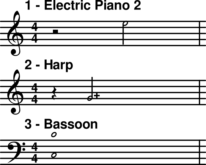
As an example, MIDI Files for the following excerpt are shown below. First, a format 0 file is shown, with all information intermingled; then, a format 1 file is shown with all data separated into four tracks: one for tempo and time signature, and three for the notes. A resolution of 96 “ticks” per quarter note is used. A time signature of and a tempo of 120, though implied, are explicitly stated.
The contents of the MIDI stream represented by this example are broken down here:
| Delta Time (decimal) | Event-Code (hex) | Other bytes (decimal) | Comment |
|---|---|---|---|
0 |
FF 58 |
04 04 02 24 08 |
4 bytes; time; 24 MIDI clocks/click, 8 32nd notes/ 24 MIDI clocks (24 MIDI clocks = 1 crotchet = 1 beat) |
0 |
FF 51 |
03 500000 |
3 bytes: 500,000 usec / quarter note = 120 beats/minute |
0 |
C0 |
5 |
Ch.1 Program Change 5 = GM Patch 6 = Electric Piano 2 |
0 |
C1 |
46 |
Ch.2 Program Change 46 = GM Patch 47 = Harp |
0 |
C2 |
70 |
Ch.3 Program Change 70 = GM Patch 71 = Bassoon |
0 |
92 |
48 96 |
Ch.3 Note On C3, forte |
0 |
92 |
60 96 |
Ch.3 Note On C4, forte |
96 |
91 |
67 64 |
Ch.2 Note On G4, mezzo-forte |
96 |
90 |
76 32 |
Ch.1 Note On E5, piano |
192 |
82 |
48 64 |
Ch.3 Note Off C3, standard |
0 |
82 |
60 64 |
Ch.3 Note Off C4, standard |
0 |
81 |
67 64 |
Ch.2 Note Off G4, standard |
0 |
80 |
76 64 |
Ch.1 Note Off E5, standard |
0 |
FF 2F |
00 |
Track End |
The entire format 0 MIDI file contents in hex follow. First, the header chunk:
4D 54 68 64 MThd
00 00 00 06 chunk length
00 00       format 0
00 01       one track
00 60       96 per quarter-note
Then the track chunk. Its header followed by the events (notice the running status is used in places):
| Delta-Time | Event | Comments |
|---|---|---|
00 |
FF 58 04 04 02 18 08 |
time signature |
00 |
FF 51 03 07 A1 20 |
tempo |
00 |
C0 05 |
|
00 |
C1 2E |
|
00 |
C2 46 |
|
00 |
92 30 60 |
|
00 |
3C 60 |
running status |
60 |
91 43 40 |
|
60 |
90 4C 20 |
|
81 40 |
82 30 40 |
two-byte delta-time |
00 |
3C 40 |
running status |
00 |
81 43 40 |
|
00 |
80 4C 40 |
|
00 |
FF 2F 00 |
end of track |
A format 1 representation of the file is slightly different. Its header chunk:
4D 54 68 64 MThd
00 00 00 06 chunk length
00 01       format 1
00 04       four tracks
00 60       96 per quarter note

4D 54 72 6B MTrk
00 00 00 14 chunk length (20)
| Delta-Time | Event | Comments |
|---|---|---|
00 |
FF 58 04 04 02 18 08 |
time signature |
00 |
FF 51 03 07 A1 20 |
tempo |
83 00 |
FF 2F 00 |
end of track |
Then, the track chunk for the first music track. The MIDI convention for note on/off running status is used in this example:
4D 54 72 6B MTrk
00 00 00 10 chunk length (16)
| Delta-Time | Event | Comments |
|---|---|---|
00 |
C0 05 |
time signature |
00 |
90 4C 20 |
tempo |
83 00 |
4C 00 |
Running status: note on, vel=0 |
00 FF 2F 00 |
end of track |
Then, the track chunk for the second music track:
4D 54 72 6B MTrk
00 00 00 0F chunk length (15)
| Delta-Time | Event | Comments |
|---|---|---|
00 |
C1 2E |
time signature |
00 |
91 43 40 |
|
83 00 |
43 00 |
running status |
00 FF 2F 00 |
end of track ‘eot’ |
Then, the track chunk for the third music track:
4D 54 72 6B MTrk
00 00 00 15 chunk length (21)
| Delta-Time | Event | Comments |
|---|---|---|
00 |
C2 46 |
time signature |
00 |
92 30 60 |
|
82 20 |
3C 60 |
running status |
83 00 |
30 00 |
two-byte delta-time, running status |
00 |
3C 00 |
running status |
00 FF 2F 00 |
end of track |
Universal System Exclusive Messages
https://www.midi.org/specifications/item/table-4-universal-system-exclusive-messages
The following table lists all currently defined Universal System Exclusive Messages. Universal System Exclusive Messages are defined as Real Time or Non-Real Time, and are used for extensions to MIDI that are NOT intended to be manufacturer exclusive (despite the name).
Many of these messages are defined in Specifications whose printed documentation is available from the MMA. Others are defined in Recommended Practice documentation that may be found on this web site.
WARNING! Details about implementing these messages can dramatically impact compatibility with other products. We strongly recommend consulting the appropriate MMA Specification or Recommended Practice for additional information.
Table: Non-Real Time (7EH)
| id1 | id2 | description |
|---|---|---|
00 |
Unused | |
01 |
Sample Dump Header | |
02 |
Sample Data Packet | |
03 |
Sample Dump Request | |
04 |
nn | MIDI Time Code |
| 00 | Special | |
| 01 | Punch In Points | |
| 02 | Punch Out Points | |
| 03 | Delete Punch In Points | |
| 04 | Delete Punch Out Points | |
| 05 | Event Start Point | |
| 06 | Event Stop Point | |
| 07 | Event Start Points with additional info. | |
| 08 | Event Stop Points with additional info. | |
| 09 | Delete Event Start Point | |
| 0A | Delete Event Stop Point | |
| 0B | Cue Points | |
| 0C | Cue Points with additional info. | |
| 0D | Delete Cue Point | |
| 0E | Event Name in additional info. | |
05 |
nn | Sample Dump Extensions |
| 01 | Loop Points Transmission | |
| 02 | Loop Points Request | |
| 03 | Sample Name Transmission | |
| 04 | Sample Name Request | |
| 05 | Extended Dump Header | |
| 06 | Extended Loop Points Transmission | |
| 07 | Extended Loop Points Request | |
06 |
nn | General Information |
| 01 | Identity Request | |
| 02 | Identity Reply | |
07 |
nn | File Dump |
| 01 | Header | |
| 02 | Data Packet | |
| 03 | Request | |
08 |
nn | MIDI Tuning Standard (Non-Real Time) |
| 00 | Bulk Dump Request | |
| 01 | Bulk Dump Reply | |
| 03 | Tuning Dump Request | |
| 04 | Key-Based Tuning Dump | |
| 05 | Scale/Octave Tuning Dump, 1 byte format | |
| 06 | Scale/Octave Tuning Dump, 2 byte format | |
| 07 | Single Note Tuning Change with Bank Select | |
| 08 | Scale/Octave Tuning, 1 byte format | |
| 09 | Scale/Octave Tuning, 2 byte format | |
09 |
nn | General MIDI |
| 01 | General MIDI 1 System On | |
| 02 | General MIDI System Off | |
| 03 | General MIDI 2 System On | |
0A |
nn | Downloadable Sounds |
| 01 | Turn DLS On | |
| 02 | Turn DLS Off | |
| 03 | Turn DLS Voice Allocation Off | |
| 04 | Turn DLS Voice Allocation On | |
0B |
nn | File Reference Message |
| 00 | reserved (do not use) | |
| 01 | Open File | |
| 02 | Select or Reselect Contents | |
| 03 | Open File and Select Contents | |
| 04 | Close File | |
| 05-7F | reserved (do not use) | |
0C |
nn | MIDI Visual Control |
| 00-7F | MVC Commands (See MVC Documentation) | |
0D |
nn | MIDI Capability Inquiry |
| 00-7F | Inquiry/Response Messages (See Documentation) | |
7B |
nn | End of File |
7C |
nn | Wait |
7D |
nn | Cancel |
7E |
nn | NAK |
7F |
nn | ACK |
Table: Non-Real Time (7EH)
Table: Real Time (7FH) - Universal System Exclusive Messages
| id1 | id2 | description |
|---|---|---|
00 |
– | Unused |
01 |
nn |
MIDI Time Code |
01 |
Full Message | |
02 |
User Bits | |
02 |
nn |
MIDI Show Control |
00 |
MSC Extensions | |
01-7F |
MSC Commands (see MSC Documentation) | |
03 |
nn |
Notation Information |
01 |
Bar Number | |
02 |
Time Signature (Immediate) | |
42 |
Time Signature (Delayed) | |
04 |
nn |
Device Control |
01 |
Master Volume | |
02 |
Master Balance | |
03 |
Master Fine Tuning | |
04 |
Master Coarse Tuning | |
05 |
Global Parameter Control | |
05 |
nn |
Real Time MTC Cueing |
00 |
Special | |
01 |
Punch In Points | |
02 |
Punch Out Points | |
03 |
(Reserved) | |
04 |
(Reserved) | |
05 |
Event Start points | |
06 |
Event Stop points | |
07 |
Event Start points with additional info. | |
08 |
Event Stop points with additional info. | |
09 |
(Reserved) | |
0A |
(Reserved) | |
0B |
Cue points | |
0C |
Cue points with additional info. | |
0D |
(Reserved) | |
0E |
Event Name in additional info. | |
06 |
nn |
MIDI Machine Control Commands |
00-7F |
MMC Commands (See MMC Documentation) | |
07 |
nn |
MIDI Machine Control Responses |
00-7F |
MMC Responses (See MMC Documentation) | |
08 |
nn |
MIDI Tuning Standard (Real Time) |
02 |
Single Note Tuning Change | |
07 |
Single Note Tuning Change with Bank Select | |
08 |
Scale/Octave Tuning, 1 byte format | |
09 |
Scale/Octave Tuning, 2 byte format | |
09 |
nn |
Controller Destination Setting (See GM2 Documentation) |
01 |
Channel Pressure (Aftertouch) | |
02 |
Polyphonic Key Pressure (Aftertouch) | |
03 |
Controller (Control Change) | |
0A |
01 |
Key-based Instrument Control |
0B |
01 |
Scalable Polyphony MIDI MIP Message |
0C |
00 |
Mobile Phone Control Message |
Table: Real Time (7FH) - Universal System Exclusive Messages
MIDI Time Code
https://www.midi.org/specifications-old/item/the-midi-1-0-specification
MIDI Time Code (MTC) is a sub-protocol within MIDI, and is used to keep 2 devices that control some sort of timed performance (ie, maybe a sequencer and a video deck) in sync. MTC messages are an alternative to using MIDI Clocks and Song Position Pointer messages. MTC is essentially SMPTE mutated for transmission over MIDI. SMPTE timing is referenced from an absolute “time of day”. On the other hand, MIDI Clocks and Song Position Pointer are based upon musical beats from the start of a song, played at a specific Tempo. For many (non-musical) cues, it’s easier for humans to reference time in some absolute way rather than based upon musical beats at a certain tempo.
There are several MIDI messages which make up the MTC protocol. All but one are specially defined SysEx messages.
The most important message is the Quarter Frame message (which is not a SysEx message). It has a status of 0xF1, and one subsequent data byte. This message is sent periodically to keep track of the running SMPTE time. It’s analogous to the MIDI Clock message. The Quarter Frame messages are sent at a rate of 4 per each SMPTE Frame. In other words, by the time that a slave has received 4 Quarter Frame messages, a SMPTE Frame has passed. So, the Quarter Frame messages provide a “sub-frame” clock reference. (With 30 fps SMPTE, this “clock tick” happens every 8.3 milliseconds).
But the Quarter Frame is more than just a quarter frame “clock tick”. The Quarter Frame message’s data byte contains the SMPTE time (ie, hours, minutes, seconds, and frames). SMPTE time is normally expressed in 80 bits. Obviously, this is too many bits to be contained in 1 8-bit data byte. So, each Quarter Frame message contains just one piece of the time (for example, one Quarter Frame may contain only the hours). In order to get the entire SMPTE time at any given point, a slave needs to receive several Quarter Frame messages, and piece the current SMPTE time together from those messages. It takes 8 Quarter Frame messages to convey the current SMPTE time. In other words, by the time that a slave can piece together the current SMPTE time, two SMPTE frames have passed (ie, since there are 4 Quarter Frame messages in each frame). So, MTC’s version of SMPTE time actually counts in increments of 2 SMPTE Frames per each update of the current SMPTE time.
The first (of 8) Quarter Frame message contains the low nibble (ie, bits 0 to 3) of the Frame Time. The second Quarter Frame message contains the high nibble (ie, bits 4 to 7) of the Frame Time. The third and fourth messages contain the low and high nibbles of the Seconds Time. The fifth and sixth messages contain the low and high nibbles of the Minutes Time. The seventh and eighth messages contain the low and high nibbles of the Hours Time. The eighth message also contains the SMPTE frames-per-second Type (ie, 24, 25, 30 drop, or 30 fps). If you were to break up the Quarter Frame’s data byte into its 7 bits, the format is:
0nnn dddd
where nnn is one of 7 possible values which tell you what dddd represents. Here are the 7 values, and what each causes dddd to represent.
| Value | dddd |
|---|---|
| 0 | Current Frames Low Nibble |
| 1 | Current Frames High Nibble |
| 2 | Current Seconds Low Nibble |
| 3 | Current Seconds High Nibble |
| 4 | Current Minutes Low Nibble |
| 5 | Current Minutes High Nibble |
| 6 | Current Hours Low Nibble |
| 7 | Current Hours High Nibble and SMPTE Type |
| Value | Meaning |
|---|---|
0xF1 0x25 |
means that the 5 is the low nibble of the Seconds Time (because nnn is 2). If the following Quarter Frame is subsequently received, |
0xF1 0x32 |
then this means that 2 is the high nibble of the Seconds Time. Therefore, the current SMPTE Seconds is 0x25 (ie, 37 seconds). |
In the data byte for the Hours High Nibble and SMPTE Type, the bits are interpreted as follows:
0nnn x yy d
where nnn is 7. x is unused and set to 0. d is bit 4 of the Hours Time. yy tells the SMPTE Type as follows:
yy |
fps |
|---|---|
| 0 | 24 |
| 1 | 25 |
| 2 | 30 (Drop-Frame) |
| 3 | 30 |
| name | value |
|---|---|
0xF1 0x0n |
where n is the current Frames Low Nibble |
0xF1 0x1n |
where n is the current Frames High Nibble |
0xF1 0x2n |
where n etc. |
0xF1 0x3n |
|
0xF1 0x4n |
|
0xF1 0x5n |
|
0xF1 0x6n |
|
0xF1 0x7n |
When MTC is running in reverse (ie, time is going backwards), these are sent in the opposite order, ie, the Hours High Nibble is sent first and the Frames Low Nibble is last. The arrival of the 0xF1 0x0n and 0xF1 0x4n messages always denote where SMPTE Frames actually occur in realtime. |
Since 8 Quarter Frame messages are required to piece together the current SMPTE time, timing lock can’t be achieved until the slave has received all 8 messages. This will take from 2 to 4 SMPTE Frames, depending upon when the slave comes online.
The Frame number (contained in the first 2 Quarter Frame messages) is the SMPTE Frames Time for when the first Quarter Frame message is sent. But, because it takes 7 more Quarter Frames to piece together the current SMPTE Time, when the slave does finally piece the time together, it is actually 2 SMPTE Frames behind the real current time. So, for display purposes, the slave should always add 2 frames to the current time.
For cueing the slave to a particular start point, Quarter Frame messages are not used. Instead, an MTC Full Frame message should be sent. The Full Frame is a SysEx message that encodes the entire SMPTE time in one message as so (in hex):
F0 7F cc 01 01 hr mn sc fr F7
cc is the SysEx channel (0 to 127). It is suggested that a device default to using its Manufacturer’s SysEx ID number for this channel, giving the musician the option of changing it. Channel number 0x7F is used to indicate that all devices on the daisy-chain should recognize this Full Frame message.
The hr, mn, sc, and fr are the hours, minutes, seconds, and frames
of the current SMPTE time. The hours byte also contains the SMPTE Type as
per the Quarter Frame’s Hours High Nibble message.
The Full Frame simply cues a slave to a particular SMPTE time. The slave doesn’t actually start running until it starts receiving Quarter Frame messages. (Which implies that a slave is stopped whenever it is not receiving Quarter Frame messages). The master should pause after sending a Full Frame, and before sending a Quarter Frame, in order to give the slave time to cue to the desired SMPTE time.
During fast forward or rewind (ie, shuttle) modes, the master should not continuously send Quarter Frame messages, but rather, send Full Frame messages at regular intervals.
SMPTE also provides for 32 “user bits”, information for special functions which vary with each product. (Usually, these bits can only be programmed from equipment that supports such). Upto 4 characters or 8 digits can be written. Examples of use are adding a date code or reel number to a tape. The user bits tend not to change throughout a run of time code, so rather than stuffing this information into a Quarter Frame, MTC provides a separate SysEx message to transmit this info.
F0 7F cc 01 02 u1 u2 u3 u4 u5 u6 u7 u8 u9 F7
cc is the SysEx channel (0 to 127). Only the low nibble of each of the
first 8 data bytes is used. Only the 2 low bits of u9 is used.
u1 = 0000aaaa
u2 = 0000bbbb
u3 = 0000cccc
u4 = 0000dddd
u5 = 0000eeee
u6 = 0000ffff
u7 = 0000gggg
u8 = 0000hhhh
u9 = 000000ii
These nibbles decode into an 8-bit format of aaaabbbb ccccdddd eeeeffff
gggghhhh ii. It forms 4 8-bit characters, and a 2 bit Format Code. u1
through u8 correspond to the SMPTE Binary Groups 1 through 8. u9 are the
2 Binary Group Flag Bits, defined by SMPTE.
The Users Bits messages can be sent at any time, whenever these values must be passed to some device on the daisy-chain.
Notation Information
There are two Notation Information messages which can be used to setup a device that needs to interact with the musician using musical bars and beats.
The Time Signature message can setup Time Signature or indicate a change of meter.
F0 7F cc 03 ts ln nn dd qq [nn dd…] F7
cc is the SysEx channel (0 to 127).
ts is 02 if the Time Signature is to be changed now, or 42 if the Time Signature is to be changed at the end of the currently playing measure.
ln is the number of data bytes following this field. Normally, this will be a 3 if there is not a compound time signature in the measure.
nn dd are the Numerator and Denominator of the Time Signature, respectively. Like with MIDI File Format’s Time Signature MetaEvent, the Denominator is expressed as a power of 2.
qq is the number of notated 32nd notes in a MIDI quarter note. Again, this is similiar to the same field in MIDI File Format’s Time Signature MetaEvent.
[nn dd …] are optional, additional pairs of num/denom, to define a compound time signature within the same measure.
The Bar Marker message indicates the start of a musical measure. It could also be used to setup and mark off bars of an introductory “count down”.
F0 7F cc 03 01 lb mb F7
cc is the SysEx channel (0 to 127).
lb mb is the desired bar number, with the LSB first (ie, Intel order). This is a signed 14-bit value (low 7 bits are in lb, right-justified, and bits 8 to 14 are in mb, right-justified). Zero and negative numbers up to -8,190 indicate count off measures. For example, a value of -1 (ie, lb mb = 7F 7F) means that there is a one measure introduction. A value of zero would indicate no count off. Positive values indicate measures of the piece. The first measure is bar 1 (ie, lb mb = 01 00). A maximum neg number (lb mb = 00 40) indicates “stopped play” condition. A maximum positive value (lb mb = 7E 3F) indicates running condition, but no idea about measure number. This would be used by a device wishing to mark the passage of measures without keeping track of the actual measure number.
Setup Message
The Setup message can be used to implement one of 19 defined “events”. A master device uses this message to tell slave units what “events” to perform, and when to perform those events. Here’s the general template for the message.
F0 7F cc 04 id hr mn sc fr ff sl sm [more info] F7
cc is the SysEx channel (0 to 127).
hr mn sc fr ff is the SMPTE time when the event is to occur. This is just like the Full Frame message, except that there is also a fractional frame parameter, ff, which is of a frame (ie, a value from 0 to 99).
sl sm is this event’s 14-bit Event Number (0 to 16,383). sl is bits 0 to 6, and sm is bits 7 to 13.
id tells what this Event Type is. Depending upon the Type, the message may have additional bytes placed where is. The following values for Event Types are defined, and here’s what each does.
Special (00)
Contains the setup information that affects a device globally, as opposed to individual tracks, sounds, programs, sequences, etc.). In this case, the Event Number is actually a word which further describes what the event is, as so:
Time Code Offset (00 00) refers to a relative Time Code offset for each unit. For example, a piece of video and a piece of music that are supposed to go together may be created at different times, and likely have different absolute time code positions. Therefore, one must be offset from the other so that they will match up. Each slave on the daisy-chain needs its own offset so that all can be matched up to the master’s SMPTE start time.
Enable Event List (01 00) means for a slave to enable execution of events in its internal “list of events” when each one’s respective SMPTE time occurs.
Disable Event List (02 00) means for a slave to disable execution of events in its internal “list of events”, but not to erase the list.
Clear Event List (03 00) means for a slave to erase all events in its internal list.
System Stop (04 00) refers to a time when the slave may shut down. This serves as a protection against Event Starts without Event Stops, tape machines running past the end of a reel, etc.
Event List Request (05 00) is sent by the master, and requests the slave (whose channel matches the message) to send all events in its list as a series of Setup messages, starting from the SMPTE time in this message.
NOTE: For the first 5 Special messages, the SMPTE time isn’t used and is ignored.
Punch In (01) and Punch Out (02)
These refer to the enabling and disabling of record mode on a slave. The Event Number refers to the track to be recorded. Multiple Punch In and Punch Out points (and any of the other Event Types below) may be specified by sending multiple Setup messages with different SMPTE times.
Delete Punch In (03) and Delete Punch Out (04)
Deletes the Punch In or Punch Out (with the matching Event Number and SMPTE Time) from the slave’s event list. In other words, it deletes a previously sent Punch In or Punch Out Setup message.
Event Start (05) and Event Stop (06)
These refer to the start/stop (ie, playback) of some continuous action (ie, an action that begins when an Event Start is received, and continues until an Event Stop is received). The Event Number refers to which action on the slave is to be started/stopped. Such actions may include playback of a specific looped waveform, a fader moving on an automated mixer, etc.
Event Start (07) and Event Stop (08) with additional info
Almost the same as the above 2 Event Types, but these have additional bytes before the final 0xF7. Such additional bytes could be for an effect unit’s changing parameters, the volume level of a sound effect being adjusted, etc. The additional info should be nibblized with the lowest bits first. For example, if the Note On message 0x91 0x46 0x7F was to be encoded in some additional info bytes, they would be 01 09 06 04 0F 07.
Delete Event Start (09) and Delete Event Stop (0A)
Deletes the Event Start or Event Stop (with the matching Event Number and SMPTE Time) from the slave’s event list. In other words, it deletes a previously sent Event Start or Event Stop Setup message (either the Types without additional info, or with additional info).
Cue Point (0B)
Sets an action to be triggered (ie, an action that does something once and automatically stops afterward) or a marker at the specified SMPTE time. These include a “hit” point for a sound effect, a marker for an edit point, etc. The Event Number should represent the action or marker. For example, Event Number 3 could be to trigger a car crash sound effect. Then, several car crashes could be specified by sending several Cue Point Setup messages, each with Event Number 3, but different SMPTE times.
Cue Point (0C) with additional info
Like the above, but this message may have additional bytes before the final 0xF7. Such additional bytes could be for an effect unit’s parameters, the volume level of a sound effect, etc. The additional info should be nibblized with the lowest bits first.
Delete Cue Point (0D)
Deletes one of the preceding 2 Setup messages (with the same Event Number and SMPTE time) from the slave’s event list.
Event Name (0E) with additional info
This assigns an ascii name to the event with the matching Event Number and SMPTE time. It for the musician’s point of reference. The additional info bytes are the ascii name. For a newline character, include both a carriage return (0x0A) and line feed (0x0D). The ascii bytes are nibblized. For example, ascii ‘A’ (0x41) becomes the two bytes, 0x01 0x04.
To summarize the interaction between master and slave depending upon “play mode”:
Play Mode
The master is in normal play at normal or vari-speed rates. The master is sending Quarter Frame messages to the slave. The messages are in ascending order, starting with 0xF1 0x0n and ending with 0xF1 0x7n. If the master is capable of reverse play, then the messages are sent in reverse, starting with 0xF1 0x7n and ending with 0xF1 0x0n.
Cue Mode
The master is being “rocked” or “cued” by hand. For example, a tape machine may have the tape still in contact with the playback head so that the musician can cue the contents of the tape to a specific point. The master is sending Quarter Frame messages to the slave. The messages are in ascending order, starting with 0xF1 0x0n and ending with 0xF1 0x7n. If the master is playing in a reverse direction, then the messages are sent in reverse, starting with 0xF1 0x7n and ending with 0xF1 0x0n. Because the musician may be changing the tape direction rapidly, the order of the Quarter Frames must change along with the tape direction.
Fast Forward or Rewind Mode
The master is rewinding or fast forwarding tape. No contact is made with the playback head. So, no cueing is happening. Therefore, the master only need send the slave periodic Full Frame messages at regular intervals as a rough indication of the master’s position. The SMPTE time indicated by the last Full Frame message actually takes affect upon the reception of the next Quarter Frame message (ie, when Play Mode resumes).
General MIDI Level 2 (1999)
General MIDI Level 2
https://en.wikipedia.org/wiki/General_MIDI_Level_2
GM2 Supported NRPN Parameter Numbers (RPN)
- Pitch Bend Sensitivity
- Channel Fine Tune
- Channel Coarse Tune
- Modulation Depth Range (Vibrato Depth Range)
- RPN NULL
Supported Universal System Exclusive (SysEx) messages
- Master Volume
- Master Fine Tuning
- Master Coarse Tuning
- Reverb Type
- Reverb Time
- Chorus Type
- Chorus Mod Rate
- Chorus Mod Depth
- Chorus Feedback
- Chorus Send to Reverb
- Controller Destination Setting
- Scale/Octave Tuning Adjust
- Key-Based Instrument Controllers
- GM2 System On
Additional Percussion Kit Key-Mappings
027 F1  High Q                     082 A#5 Shaker
028 F#1 Slap                       083 B5  Jingle Bell
029 G2  Scratch Push               084 C5  Belltree
032 G#1 Scratch Pull               085 C#5 Castanets
033 A1  Sticks                     086 D5  Open Surdo
034 A#1 Metronome Bell
BANK 1
Key: [BANK-MSB]:[BANK-LSB] [Patch-Name]
001:001 Wide Acoustic Grand        001:054 Humming
001:002 Wide Bright Acoustic       001:055 Analog Voice
001:003 Wide Electric Grand        001:056 Bass Hit
001:004 Wide Honky-tonk            001:057 Dark Trumpet
001:005 Detuned Electric Piano 1   001:058 Trombone 2
001:006 Detuned Electric Piano 2   001:060 Muted Trumpet 2
001:007 Coupled Harpsichord        001:061 French Horn 2
001:008 Pulse Clavinet             001:062 Brass Section 2
001:012 Wet Vibraphone             001:063 Synth Brass 3
001:013 Wide Marimba               001:064 Synth Brass 4
001:015 Church Bell                001:081 Square Wave
001:017 Detuned Organ 1            001:085 Wire Lead
001:018 Detuned Organ 2            001:088 Delayed Lead
001:020 Church Organ 2             001:090 Sine Pad
001:021 Puff Organ                 001:092 Itopia
001:022 Italian Accordion          001:099 Synth Mallet
001:025 Ukulele                    001:103 Echo Bell
001:026 12-String Guitar           001:105 Sitar 2
001:027 Hawaiian Guitar            001:108 Taisho Koto
001:028 Chorus Guitar              001:116 Castanets
001:029 Funk Guitar                001:117 Concert Bass Drum
001:030 Guitar Pinch               001:118 Melodic Tom 2
001:031 Feedback Guitar            001:119 808 Tom
001:032 Guitar Harmonics           001:121 Guitar Cut Noise
001:034 Finger Slap                001:122 Flute Key Click
001:039 Synth Bass 101             001:123 Rain
001:040 Synth Bass 4               001:124 Dog
001:041 Slow Violin                001:125 Telephone 2
001:047 Yang Qin                   001:126 Car-Engine
001:049 Orchestra Strings          001:127 Laughing
001:051 Synth Strings 3            001:128 Machine Gun
001:053 Choir Aahs 2
BANK 2
002:001 Dark Acoustic Grand         002:056 6th Hit
002:005 Electric Piano 1 Variation  002:058 Bright Trombone
002:006 Electric Piano 2 Variation  002:063 Analog Brass 1
002:007 Wide Harpsichord            002:064 Analog Brass 2
002:015 Carillon                    002:081 Sine Wave
002:017 60’s Organ 1                002:082 Doctor Solo
002:018 Organ 5                     002:103 Echo Pan
002:020 Rock Organ                  002:119 Electric Percussion
002:025 Open Nylon Guitar           002:121 Horse-Gallop
002:026 Mandolin                    002:123 Thunder
002:028 Mid Tone Guitar             002:124 Horse-Gallop
002:029 Funk Guitar 2               002:125 Door Creaking
002:031 Distortion Rtm Guitar       002:126 Car-Stop
002:039 Synth Bass 3                002:127 Screaming
002:040 Rubber Bass                 002:128 Lasergun
002:049 60’s Strings
BANK 3
003:005 60’s Electric Piano        003:056 Euro Hit
003:006 Electric Piano Legend      003:063 Jump Brass
003:007 Open Harpsichord           003:082 Natural Lead
003:017 Organ 4                    003:123 Wind
003:025 Nylon Guitar 2             003:124 Bird 2
003:026 Steel + Body               003:125 Door Closing
003:029 Jazz Man                   003:126 Car-Crash
003:039 Clavi Bass                 003:127 Punch
003:040 Attack Pulse               003:128 Explosion
BANKS 4-8
004:006 Electric Piano Phase       005:123 Bubble
004:039 Hammer                     005:125 Wind Chimes
004:082 Sequenced Saw              005:126 Siren
004:123 Stream                     005:127 Footsteps
004:125 Scratch
004:126 Car-Crash
004:127 Heart Beat

006:126 Train                      007:126 Jetplane

008:126 Starship
Additional Standards
Generally GS MIDI Standards foreshadowed what seems to have become
General MIDI Layer 2 (GM2).
Yamaha XG is worth checking out in addition to the XGLite standard.
MIDI Standard Comparison
https://en.wikipedia.org/wiki/Comparison_of_MIDI_standards
DLS (Y—I’m sure you can find much more adequate links)
https://www.loc.gov/preservation/digital/formats/fdd/fdd000118.shtml
Footnotes
-
“The MIDI Association” — https://www.midi.org ↩
-
“Society of Motion Picture and Television Engineers” — https://www.smpte.org ↩
-
“Microseconds” 1,000,000 = 1 microsecond; e.g. µsec, usec, musec ↩